ICAO standards for obstruction lights, Chapter 6 of ICAO Annex 14
ICAO Standards for Obstruction Lights: Ensuring Safety in Aviation
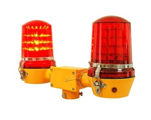
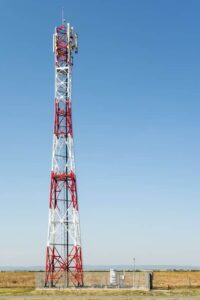
The International Civil Aviation Organization (ICAO) sets strict standards for obstruction lighting to ensure the safety of aircraft in flight. Obstruction lights are used to mark tall structures like telecom towers, transmission lines, and buildings that pose potential hazards to aircraft. These lights must be visible to pilots from a distance, regardless of weather or time of day.
Types of Obstruction Lights
ICAO defines several types of obstruction lights based on intensity and purpose:
- Low-Intensity Lights: These are used for structures under 45 meters in height. They emit a steady red light and are visible during nighttime.
- Medium-Intensity Lights: These are suitable for structures between 45 to 150 meters. They flash white during the day and red at night.
- High-Intensity Lights: For structures taller than 150 meters, high-intensity lights flash white and are visible in all conditions.
Chapter 6 of ICAO Annex 14 Volume I “Aerodrome Design and Operations”, ICAO regulates obstacle lighting’s photometric characteristics. Furthermore some recommendations are clarified about how to deploy obstruction lights for different heights of structures. Aviation Warning Light’s intensity characteristics and recommended configuration are referenced from ICAO Annex 14 Volume I “Aerodrome Design and Operations”, 8th Edition, July 2018.

Photometric characteristics and distributions of obstacle lights
| Light Type | Color | Signal type (flash rate) | Peak intensity (cd) at given background luminance | Vertical beam spread | Vertical elevation angle (minimum requirements) | ||
|---|---|---|---|---|---|---|---|
| Day (Above 500cd/m2) | Twilight (50- 500cd/m2) | Night (Below 50cd/m2) | |||||
| Low-intensity, Type A (fixed obstacle) | Red | Fixed | N/A | N/A | ≥10cd | ≥10° | +2° - +10° |
| Low-intensity, Type B (fixed obstacle) | Red | Fixed | N/A | N/A | ≥32cd | ≥10° | +2° - +10° |
| Low-intensity, Type C (mobile obstacle) | Yellow/Blue | Flashing (60-90fpm) | N/A | ≥40cd | ≥40cd & ≤400cd | ≥12° | +2° - +20° |
| Low-intensity, Type D (follow-me obstacle) | Yellow | Flashing (60-90fpm) | N/A | ≥200cd | ≥200cd & ≤400cd | N/A | N/A |
| Low-intensity, Type E (fixed obstacle) | Red | Flashing (20-60fpm) | N/A | N/A | ≥32cd | ≥10° | +2° - +10° |
| Light Type | Color | Signal type (flash rate) | Peak intensity (cd) at given background luminance | Vertical beam spread (min. requirements) | Vertical beam spread (recommended requirements) | Intensity at Vertical elevation angle (minimum requirements) | Intensity at Vertical elevation angle (recommended requirements) | |||||
|---|---|---|---|---|---|---|---|---|---|---|---|---|
| Day (Above 500cd/m2) | Twilight (50- 500cd/m2) | Night (Below 50cd/m2) | 0° | -1° | 0° | -1° | -10° | |||||
| Medium-intensity, Type A | White | Flashing (20-60fpm) | 20,000cd±25% | 2,000cd±25% | 2,000cd±25% | ≥3° | NA | Day: mean: ≥20,000cd, min.: ≥15,000cd;Night: mean: ≥2,000cd, min.: ≥1,500cd; | Day: ≥7,500cd; Night: ≥750cd; | Day: ≤25,000cd; Night: ≤2,500cd | Day: ≤11,250cd; Night: 1,125cd | Day: ≤750cd; Night: ≤75cd |
| Medium-intensity, Type B | Red | Flashing (20-60fpm) | N/A | N/A | 2,000cd±25% | ≥3° | NA | mean: ≥2,000cd, min.: ≥1,500cd; | ≥750cd | ≤2,500cd | ≤1,125cd | ≤75cd |
| Medium-intensity, Type C | Red | Fixed | N/A | N/A | 2,000cd±25% | ≥3° | NA | mean: ≥2,000cd, min.: ≥1,500cd; | ≥750cd | ≤2,500cd | ≤1,125cd | ≤75cd |
| High-intensity, Type A | White | Flashing (40-60fpm) | 200,000cd±25% | 20,000cd±25% | 2,000cd±25% | ≥3° | ≤7° | Day: mean: ≥200,000cd, min.: ≥150,000cd; Twilight: mean: ≥20,000cd, min.: ≥15,000cd; Night: mean: ≥2,000cd, min.: ≥1,500cd; | Day: ≥75,000cd; Twilight: 7,500cd Night: ≥750cd; | Day: ≤250,000cd; Twilight: ≤25,000cd; Night: ≤2,500cd | Day: ≤112,500cd; Twilight: ≤11,250cd; Night: ≤1,125cd | Day: ≤7,500cd; Twilight: ≤750cd; Night: ≤75cd |
| High-intensity, Type B | White | Flashing (40-60fpm) | 100,000cd±25% | 20,000cd±25% | 2,000cd±25% | ≥3° | ≤7° | Day: mean: ≥100,000cd, min.: ≥75,000cd; Twilight: mean: ≥20,000cd, min.: ≥15,000cd; Night: mean: ≥2,000cd, min.: ≥1,500cd; | Day: ≥37,500cd; Twilight: 7,500cd Night: ≥750cd; | Day: ≤125,000cd; Twilight: ≤25,000cd; Night: ≤2,500cd | Day: ≤56,250cd; Twilight: ≤11,250cd; Night: ≤1,125cd | Day: ≤3,750cd; Twilight: ≤750cd; Night: ≤75cd |
Light Placement and Visibility
According to ICAO standards, obstruction lights must be placed at the highest points of the structure. If the tower or building has multiple levels, lights should also be installed at intermediate heights to ensure full visibility. For large structures, lights must be arranged so they are visible from all angles of approach.
The intensity of the light should be strong enough to ensure visibility during day and night. ICAO mandates that lights must be visible for a minimum distance, depending on their intensity. For example, high-intensity lights should be visible from up to 20 kilometers away during the day.

Importance of ICAO Compliance
Adhering to ICAO standards is essential for ensuring that obstruction lights meet global safety requirements. The standards guarantee that aircraft, especially those flying at low altitudes, can easily identify potential hazards. Non-compliance could lead to accidents, so using lights that meet these standards is crucial.
Power Supply and Backup
Obstruction lights must be powered by a reliable source. ICAO also recommends having backup power systems, such as generators or batteries, in case of power failure. This ensures continuous operation even during outages, protecting aircraft and infrastructure.

Conclusion
ICAO standards for obstruction lights ensure safety in aviation by clearly marking hazards in flight paths. Whether it’s a telecom tower or a tall building, complying with these regulations guarantees that the structure is visible to pilots, reducing the risk of collisions.
As part of its comprehensive telecom and infrastructure solutions, MTS Tower offers a range of ICAO-compliant obstruction lights, designed to ensure maximum visibility and safety. Our obstruction lights are engineered to meet international standards, providing consistent performance in both urban and remote locations.
MTS Tower also provides turnkey solutions for installation and maintenance of these lights, ensuring they meet ICAO standards for placement, intensity, and power reliability. In addition, MTS Tower supplies generator sets as backup power sources for obstruction lighting systems, ensuring continuous operation in case of power failure.