Transmission Line Towers
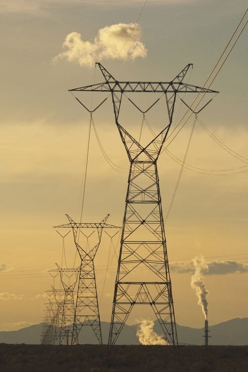
Energy transmission line towers are large, robust structures designed to support overhead power lines, ensuring the safe and efficient transmission of electricity over long distances. These towers are typically made from steel and are engineered to withstand various environmental conditions, including wind, ice, and seismic activity.
Transmission line towers are critical components in the electrical grid, used to transport high-voltage electricity from power plants to substations, where it is then distributed to homes and businesses. They are available in different configurations, such as lattice towers, tubular towers, and monopole towers, depending on the terrain, voltage capacity, and environmental needs.
Engineered for durability, energy transmission line towers must adhere to strict safety and performance standards to ensure reliable power delivery, even in remote or challenging landscapes. They play a vital role in maintaining the integrity and stability of power networks worldwide.
Furthermore MTS Tower supply transmission towers for high-voltage lines ranging from 345 kV, 500 kV, 735 kV to 765 kV.
What is Overhead Transmission Line Towers ?
Transmission lines are categorized based on several factors, such as voltage levels, structure design, and the medium used for power transmission. Here are the common types:
Overhead Transmission Lines
- High Voltage (HV): Typically operates between 35kV and 230kV. Used for long-distance transmission of electricity.
- Extra High Voltage (EHV): Operates between 230kV and 765kV. These lines are used for very long distances and large-scale power distribution.
- Ultra High Voltage (UHV): Voltage levels above 765kV, used for the longest transmission distances and very large loads.
- Medium Voltage (MV): Ranges from 1kV to 35kV, mainly used for local distribution and regional transmission.
Design Types:
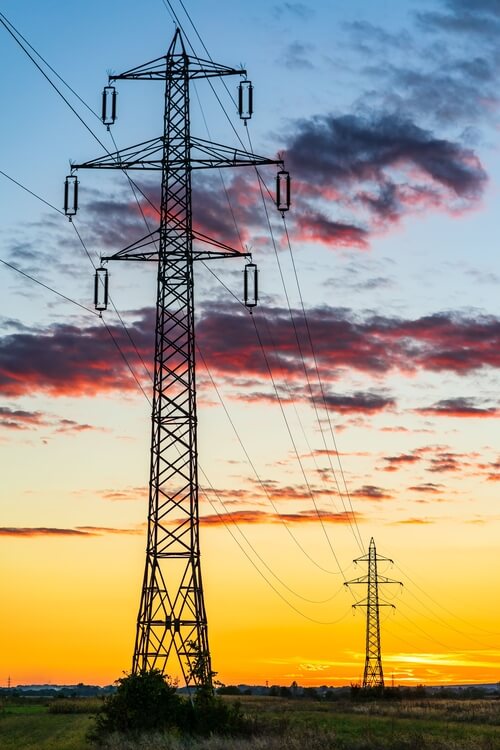
- Lattice Towers: The most common, made of steel and offering robust support for long spans.
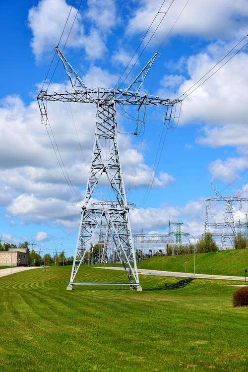
- Tubular Towers: Sleek and visually less intrusive, often used in urban areas.
- Monopole Towers: Single-pole structures used when space is limited.
- Guyed Towers: Supported by guy wires, these are cost-effective and used in areas where space is available for anchoring.
Tower Types
Transmission towers are classified based on their function within the power grid. Here are some key types, including Dead-End and Tension Towers:
1. Dead-End Towers (also known as Terminal or Anchor Towers)
- Function: These towers are used where the transmission line terminates or where there is a sharp change in direction. Dead-end towers anchor the conductors at the end of a line or at a key point in the transmission route.
- Design: They are robust and reinforced to withstand the tension from the lines, as they carry the load from one direction without relying on tension from the next span.
- Application: Used at the beginning or end of a transmission line or at critical points like river crossings, highway crossings, or substations.
2. Tension Towers (or Strain Towers)
- Function: These towers are designed to handle significant tension and mechanical stress. They are used when the line makes a sharp angle (usually 10 degrees or more) or in locations with high wind or uneven terrain. They also help control the sag of the conductors.
- Design: Heavier and more reinforced than regular towers to hold the mechanical tension in the conductors. They are often placed at points of directional change or where terrain alters the conductor span.
- Application: Found at angles in the transmission line route or where line tension is a concern.
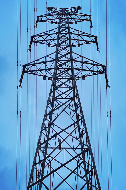
3. Suspension Towers (or Tangent Towers)
- Function: These towers support the conductors between dead-end or tension towers. They are designed to simply carry the weight of the transmission lines with minimal mechanical stress.
- Design: Typically less robust than dead-end or tension towers because they are not subjected to high tension forces.
- Application: Used for straight, continuous spans between tension or dead-end towers.
4. Transposition Towers
- Function: These towers are used to change the relative positions of the conductors on the tower, balancing out the electromagnetic interference (EMI) that can occur along the line.
- Application: Placed at specific intervals to equalize the electrical load and reduce interference.
5. Crossing Towers
- Function: These towers are designed for long spans to cross rivers, highways, or other wide obstacles. They need to support the long stretch of conductor and handle additional stress.
- Design: Taller and sturdier than standard towers, often featuring guy wires or stronger materials for additional support.
- Application: Used in locations where transmission lines cross large rivers, valleys, or highways.
6. Guide Towers
- Function: Guide towers are typically used at river or highway crossings to guide conductors to the proper height and clearance.
- Design: Similar to suspension towers but designed to hold conductors in a specific configuration to clear the obstacle safely.
7. Branching Towers (also called Junction Towers)
- Function: These towers support branching lines, where a single transmission line splits into two or more directions.
- Design: Equipped to handle the additional stress from multiple line directions.
Each type of tower plays a critical role in the transmission system, ensuring the safe, efficient, and reliable delivery of electricity. The choice of tower depends on the location, terrain, and the mechanical and electrical requirements of the transmission line.