Guyed Mast vs. Self-Supported Towers: Choosing the Right Infrastructure

Is the self supported towers best choice or guyed mast will be ideal?
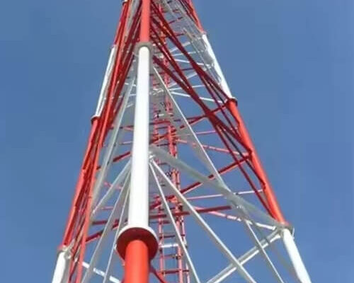
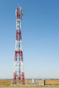
Choosing between a guyed mast and a self-supported tower is a critical decision for any modern telecommunications project.
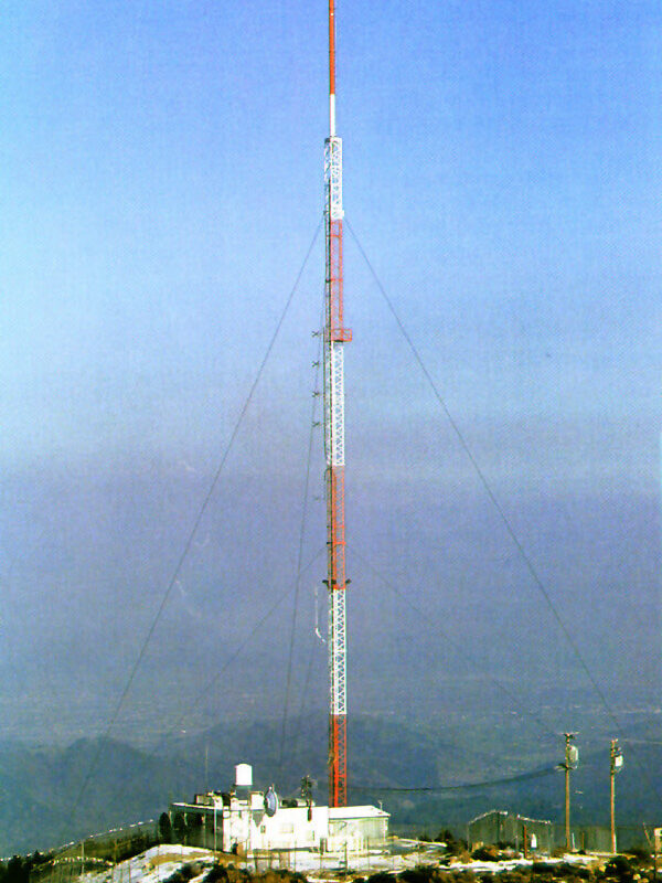
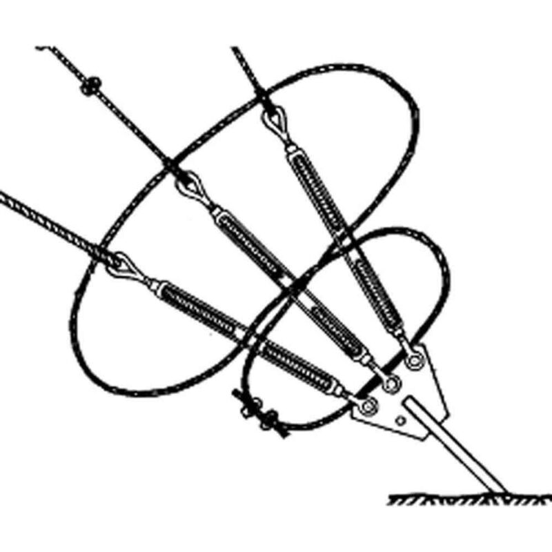
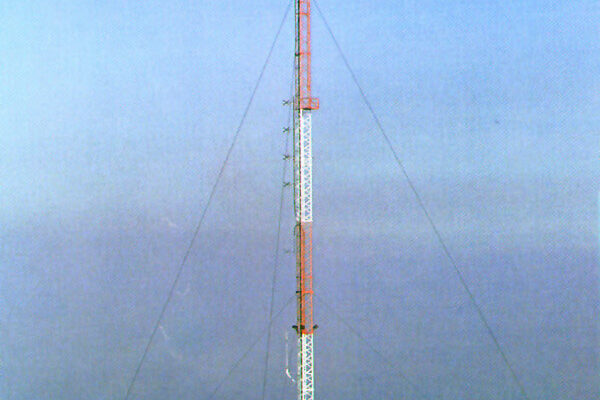
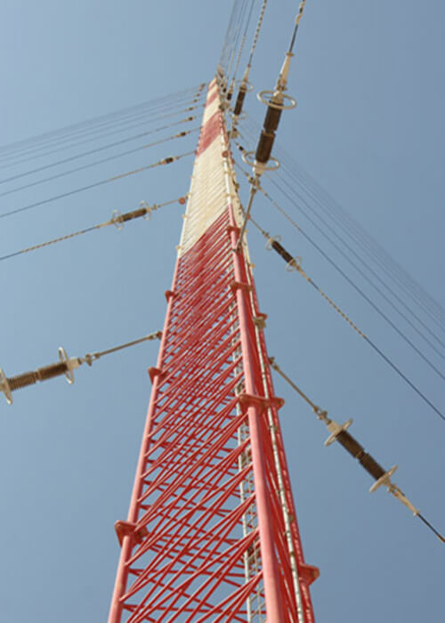
In general, engineers use guyed masts for high-altitude broadcasting in rural areas where land is cheap and plentiful. Specifically, these thin structures rely on anchored wires to stay upright, making them very cost-effective for reaching extreme heights.
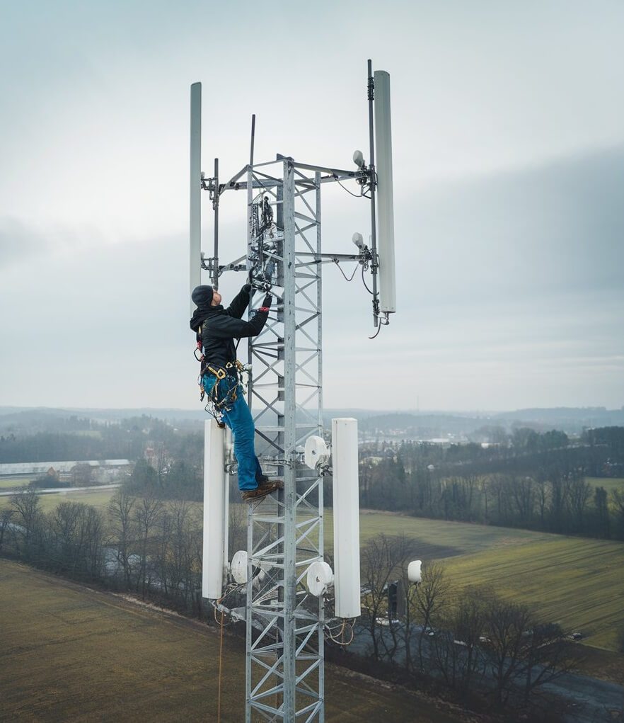
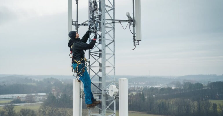
On the other hand, builders prefer self-supported towers for urban 5G network expansion. Because these towers stand independently on a heavy base. Also, They require a much smaller footprint.
As a result, they fit perfectly in crowded city centers or on top of buildings where space is limited.
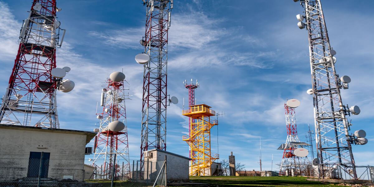
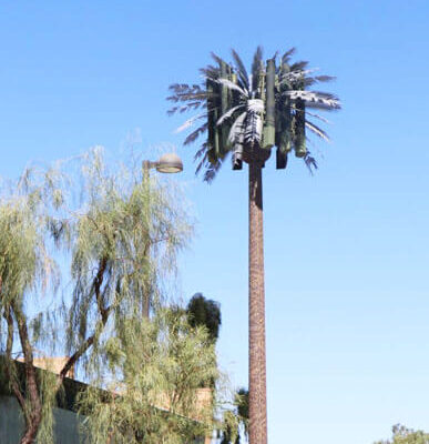
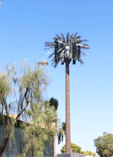
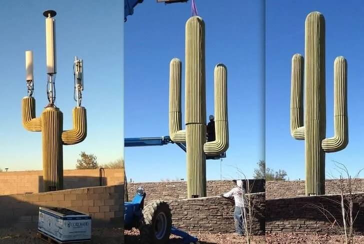
Furthermore, Engineers build towers in different styles — lattice, monopole, guyed, or camouflaged — depending on site conditions and coverage requirements.

Furthermore, both tower types must adhere to strict TIA-222-H structural engineering standards to ensure they handle wind and ice loads safely. While guyed masts are cheaper to manufacture, they require constant maintenance of the tension wires.
Conversely, self-supported lattice towers offer a “set-and-forget” level of durability. Ultimately, the best choice depends on your site’s geography and the weight of the antennas you plan to install.
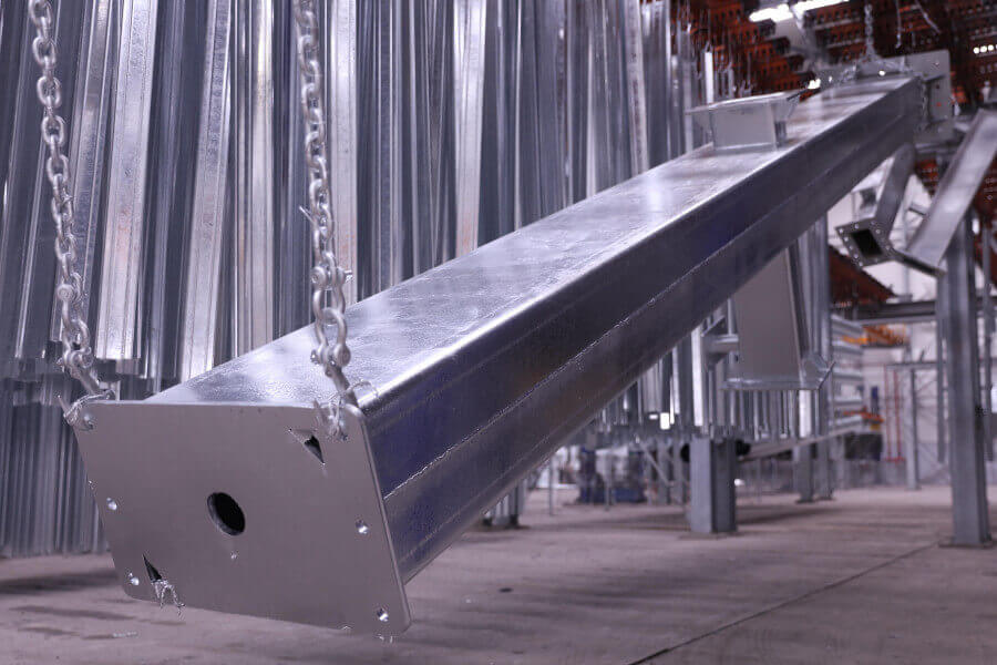
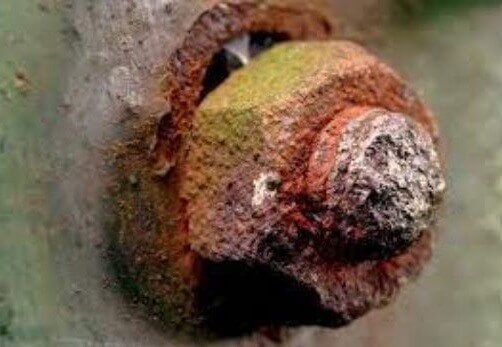
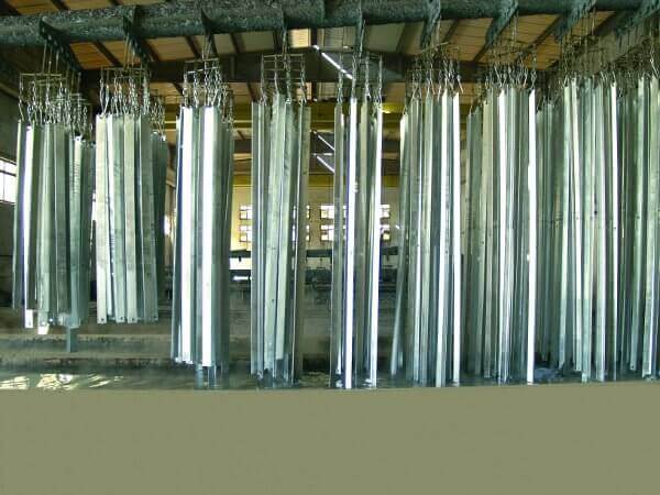
Using high-quality, hot-dip galvanized steel ensures that whichever structure you choose, it will resist rust and remain efficient for decades.
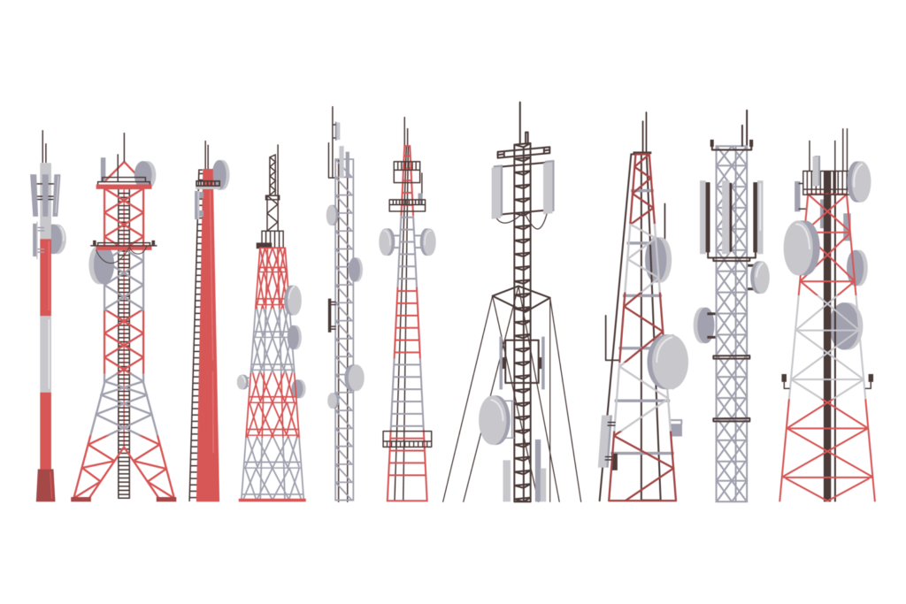
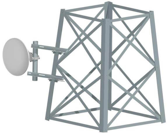
Common Types of Self-Supported Towers
Engineers typically classify self-supporting structures into three main categories based on their geometry and the steel profiles used:
- three-legged lattice,
- four-legged lattice,
- monopoles.
Specifically, the three-legged lattice tower is the global standard for cost-effective rural coverage. Because it uses roughly 20-30% less steel than a square tower, it significantly lowers your initial investment and shipping costs. However, for high-capacity sites, the four-legged lattice tower is the superior option. In fact, its square base offers the highest torsional rigidity, which is essential for supporting heavy 5G massive MIMO antenna arrays and surviving extreme “Risk Category IV” wind zones.
Angular or Tubular Tower
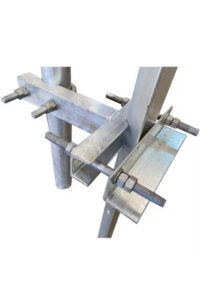
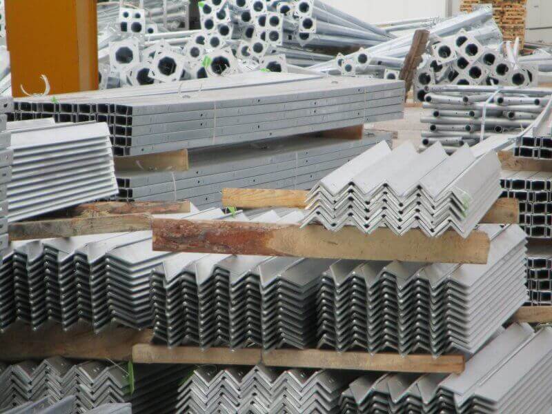
In addition, you must decide between angular and tubular steel members. Basically, Angular steel (L-profiles) is a favorite for international projects because the pieces “nest” together, allowing for efficient flat-packed shipping.
Conversely, tubular steel members provide a sleek, aerodynamic profile that reduces wind drag. Consequently, tubular towers often require smaller foundations, saving you money on concrete and labor during installation.
Finally, monopoles offer the smallest footprint of all. Therefore, they are the best choice for self supported tower type for urban centers where land is expensive and aesthetics are a priority.
Comparison Table for Guyed Mast & Self Supported Towers
| Tower Type | Drawbacks (Cons) | Benefits (Pros) | Best Application |
|---|---|---|---|
| 3-Legged Lattice | (-) Lower load capacity; less rigid in high winds. | (+) Most economical; uses less steel; fast to erect. | Rural GSM & LTE networks; remote hills. |
| 4-Legged Lattice | (-) Highest material cost; requires more ground space. | (+) Maximum stability; supports the heaviest antenna loads. | 5G Hubs; Broadcast (TV/Radio); Coastal sites. |
| Monopole | (-) Limited height (usually <60m); higher cost per meter. | (+) Smallest footprint; fast "stack" installation; easy to hide. | Urban streets; private enterprise 5G; parking lots. |
| Angular Steel | (-) Industrial look; higher wind resistance than tubes. | (+) Lowest manufacturing cost; easiest to ship globally. | Standard B2B exports; remote infrastructure. |
| Tubular Steel | (-) More expensive to produce; harder to galvanize internally. | (+) Aerodynamic; aesthetically pleasing; high buckling strength. | High-wind zones; architectural projects. |

Engineering Standards & Compliance
Regardless of the type, all structures on MTS TOWER are designed to meet the TIA-222-H standard.
Additionally, this ensures that your tower can withstand site-specific environmental loads, including:
-
Ultimate Wind Speeds: Calculated based on local 50 or 100-year return periods.
-
Ice Loading: Essential for cold climates like Canada or Northern Europe.
-
Seismic Resilience: Ensuring the structure remains operational after an earthquake.
- Also, we consider these standards for guyed mast and self supported towers.
Why Quality Matters in tower manufacturing ?
Every structure mentioned above must comply with TIA-222-H standards to ensure public safety. Ultimately, using sustainable, low-carbon steel with high-quality galvanization protects your investment from corrosion.
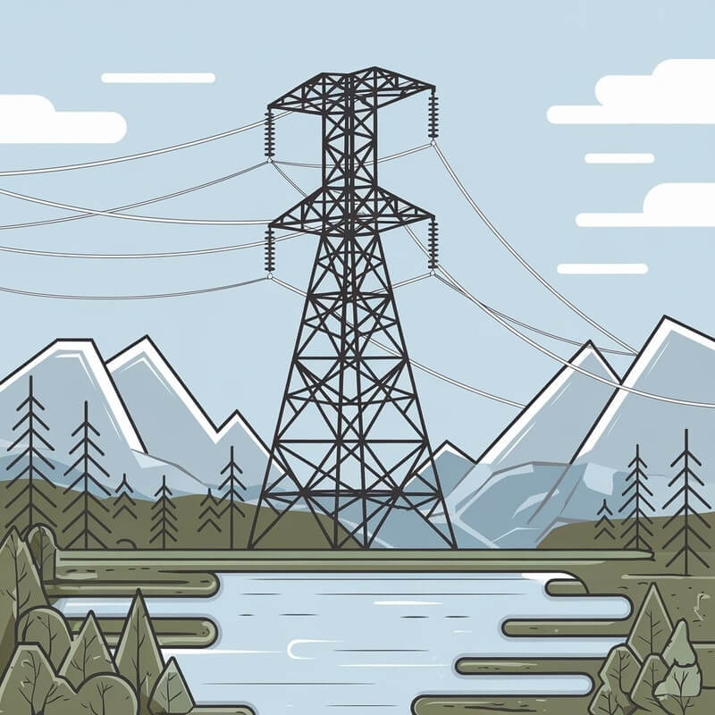
Therefore, whether you are building a 5G hub or a remote power line, choosing the right structural design is the first step toward long-term success.

MTS Tower Quality Advantages: Engineering Excellence and Durability
At MTS TOWER, quality is the cornerstone of every structure we manufacture. In fact, we prioritize the highest international standards. Also, We ensure that our telecom and energy towers provide long-term reliability.
Specifically, our manufacturing process follows the ISO 9001 Quality Management System, which guarantees consistency from raw material selection to final delivery. Furthermore, we design all our towers to comply with the latest TIA-222-H structural standards.
Also, this rigorous engineering approach ensures that our structures withstand extreme wind, ice, and seismic loads. As a result, clients receive infrastructure that is not only safe but also future-proof for next-generation network expansions.
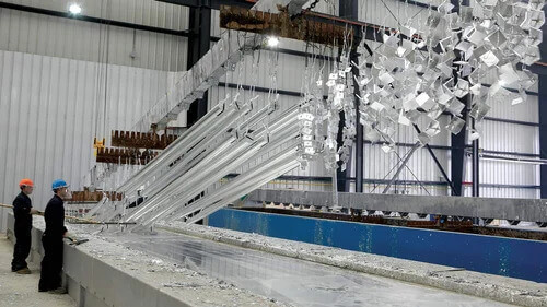
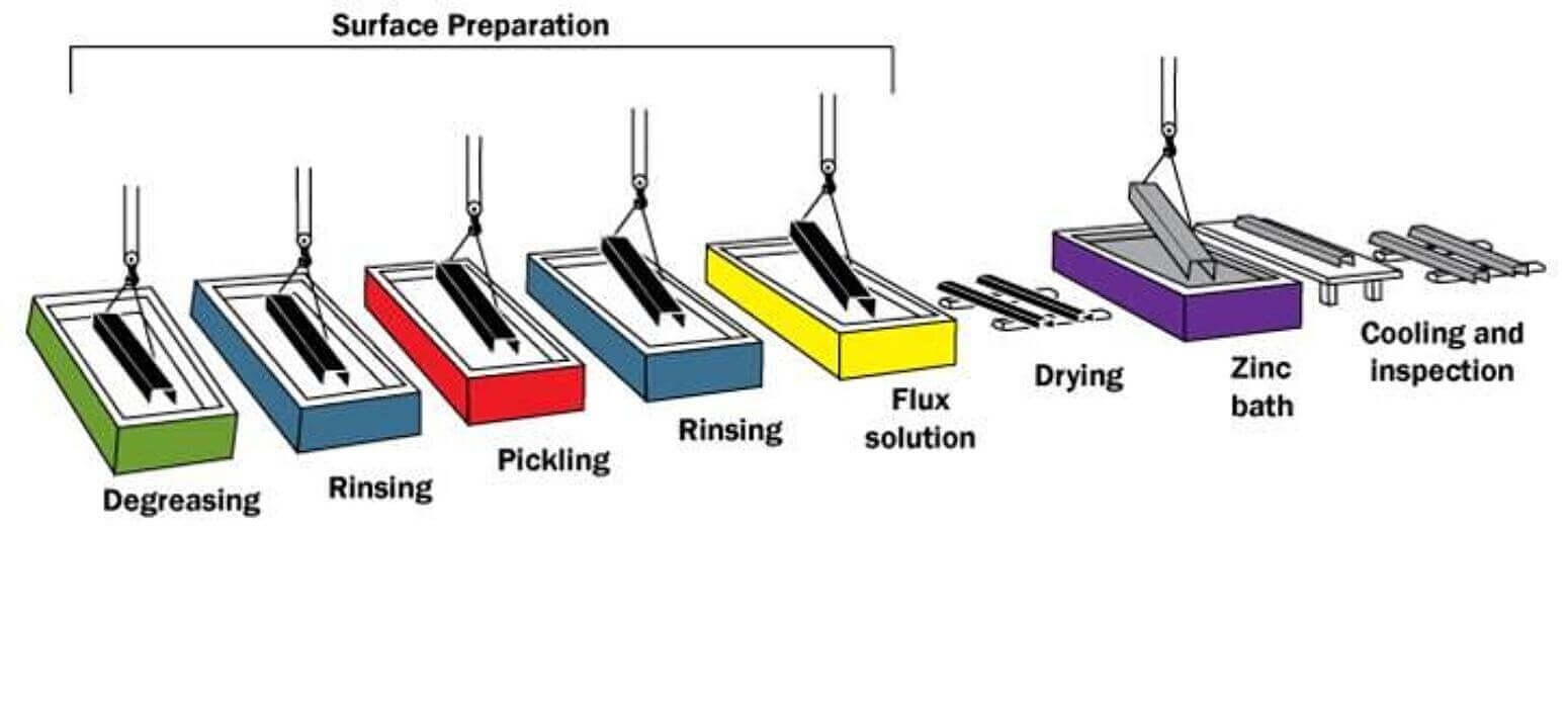
In addition to structural integrity, we focus heavily on corrosion resistance. Specifically, every steel component undergoes a premium hot-dip galvanization process in accordance with ISO 1461 and ASTM A123 standards.
Because this metallurgical bond creates a thick protective layer, our towers remain rust-free even in harsh coastal or industrial environments.
Moreover, our dedicated engineering team performs Finite Element Analysis (FEA) and prototype testing to verify every design before mass production.
Ultimately, choosing MTS Tower means investing in precision-engineered solutions that offer a longer service life and significantly lower maintenance costs.